EE
2212
PROBLEM
SET 6
S.
G. Burns
Due: Wednesday, 12 March 2014
Note 1: Problems 3 and 4 are “plug and chug” to
help you familiarize yourself with the numbers and units for FETs.
Note 2: Table 4.6 on Page 204 provides useful
information if these data are not provided in any of the Chapter 4 problems.
1.
This problem is derived
from an old quiz. The
I-V curves for a Si solar panel are shown below. The area of the solar panel is 0.5 m2.
Provide a
number for:
(a) VOC, Open Circuit Voltage___________ and ISC,
Short Circuit Current ________________
(b) Estimate a value for
the maximum output power of this panel and illustrate, on the graph, how you obtained
this value.
(c) Using a reasonably
accepted value for the solar constant, estimate the efficiency of this panel
using your results from Part (b).
(d) The solar panel
array on the top of Malosky stadium has a peak power generating capability
of 5.6 KW. Briefly explain what attributes are
required for the interface
electronics to connect this array to the power grid.

2. Text
3.123 Sketch the
curve manually or use MATLAB, EXCEL or some other function curve program to illustrate your
answers. Figure 3.73 should provide some
guidance as well as the curve in Problem 1.
3. Text
Problems 4.1 and 4.2 and for 4.2, observe that this is Cox, capacitance per unit
area. Watch your units. Usually capacitance/cm2 are preferred for
the capacitance per unit area units. When the text and in the industry talks
about an MOS capacitor, they are usually referring to capacitance/unit area.
The total capacitance can then be scaled by the W x L product. This idea of scaling is a very important VLSI
design concept. The parallel plate basic
capacitor model works well!
4. Text
4.4 and 4.8 for NMOS and Text 4.48 for PMOS. Organize your results in a table.
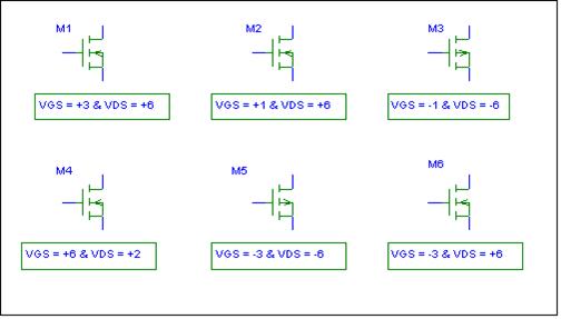
5. From
an old quiz. For the indicated bias
conditions, state whether the FET is operating in the OHMIC (TRIODE) region,
SATURATION region, or CUTOFF region.
Explain your reasoning. Assume
that |VT | = 2
volts for both the NMOS and PMOS enhancement mode transistors.
M1
__________ M2 __________ M3 __________
M4 __________ M5
__________ M6 __________
All
of these cartoons are relevant my life at UMD.
(1) I have my own coffee pot to avoid issues.
(2) I have a slide rule collection and even know
how to use them. Let me know if you want
a short course. In their day, prior to
the early 70s, slide rules were a great tool to learn about log10
theory and applications.
(3) The iPAD and Macbook are so friendly and the graphics are great, but I
can’t find a good SPICE APP.
(4) For those of you who are aware of the current
UMD budget issues, the Dilbert cartoon says it all. ENJOY!


Recall
the WOM (Write-Only-Memory) Signetics Data Sheet from the attachment to the
diode experiment. I think those
engineers may have taken a clue from some engineers at EIMAC. The EIMAC division manufactures high power
and specialty vacuum tubes used in high power transmitters and RF generators
and related. This is a data sheet for the “PHANTASATRON”. EIMAC is now a
subsidiary of Communications and Power Industries. Even though small vacumm tubes are no longer
made in the U.S., there are some manufacturers in Russia and Brazil catering to
the high end audiophile market. Larger,
high power transmitting tubes and speciality vacuum tubes are manufactured by
EIMAC and others. Enjoy!