In this lab, you will get hands-on experience connecting to routers and switches on the Network Testbench. The lab is intended to make you familiar with how we can connect (and control) the routers on the rack. You will start by using the lab's computers to connect to the routers using our Avocent Cyclades ACS (Advanced Console Server) box. Once connected, you will use a few basic Cisco IOS commands to interact with the router.
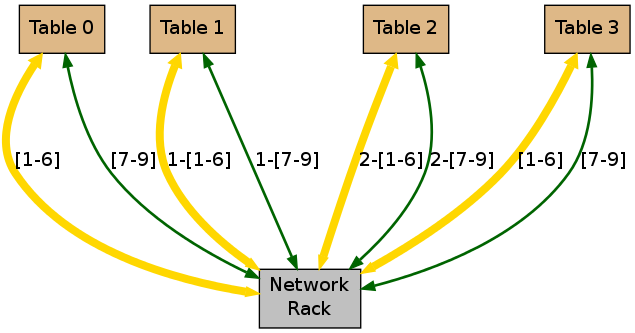
The rack itself is in the back room in the MWAH 187 Lab. The TA will open up the door to give you when it needs to be accessed directly. The lab is physically setup so that four bundles containing 6 yellow and 3 green CAT6 Ethernet cable go from the rack to each of the tables in the lab. This setup is illustrated below:
It is worth noting the labeling on the yellow cables. The labeling is meant to indicate first the table to which the bundle goes and then the number of the cable within the bundle. An error in labeling left off the '0' for table 0's cable bundles So, Cable 2-1 is the first computer on Table 2. The yellow cables connect directly to the desktop PCs at each table and go back to the rack. The green cables are extras and may allow us ability to connect in other devices to the rack if need be in the future (for instance, your own laptops). It may be worth investigating the yellow cable that plugs into your machine and then locating where exactly it plugs in at the rack.
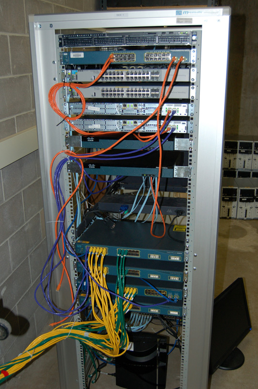
The equipment on the rack consists of the following equipment (listed in order from top of the rack to the bottom): 1 rack-mounted HP 1U Server, 1 Cisco Catalyst 3560 Switch, 2 HP Switch Routers, 2 Cisco 2811 XM Routers, 2 Cisco 1921 Routers, and 4 Cisco Switches of various types. A folding, pull-out VGA display that connects to the server machine is sandwiched between the equipment. At the very bottom of the rack is an Avocent Cyclades ACS console server to provide access to all of the consoles on the routers and switches. Other machines are connected to the system and are stored in the backroom. A picture of most of this equipment is shown below:
To begin, I want you to create a map (or graph) of the topology of the network rack. As we've indirectly seen in class, network topology is often best and most easily represented as a graph structure. You can create a picture of a graph using the GraphViz program. GraphViz is free and available on many systems. You will have to install it on the machines in the lab (the Ubuntu package name is graphviz; [sudo apt-get install graphviz]).
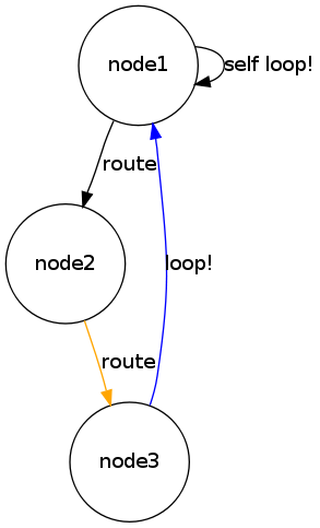
GraphViz can be used to draw all sorts of graphs. GraphViz takes ASCII files describing the graph structure as input and outputs JPG or PNG or other files. GraphViz is really a collection of graph drawing tools. The one we are interested in using is dot. To show you how simple it really is, here's a very simple digraph file (myGraph.txt) that connects three nodes:
digraph simple
{
 node [shape = circle];
 node1 -> node2 [ label = "route" ];
 node2 -> node3 [ color=orange, label = "route" ];
 node1 -> node1 [ label = "self loop!" ];
 node3 -> node1 [ color=blue, label = "loop!" ];
}
The "node[shape = circle]" line simply tells dot to use circles for the node representations; there are rectangles, squares, and other forms. The associated graph is created by running the following command:
dot -Tpng -o simpleGraph.png myGraph.txt
This creates the simpleGraph.png file shown below.
You now have a way to create a map of the network topology. That will be the first part of the lab exercise.
In the first part of the lab, you should work together by table or slightly larger groups to come up with the physical topology of the network rack. By working together, I think it might be easiest if small groups of people work to see which machines connect to each other and how they connect to each other. Compile this information at the rack itself (the TA or myself will give you access to the back room), and then go to the lab machines and write up a DOT ascii description of the configuration and create a graph of the topology.
Once you get your map created, you can move on to Part 2. Note that you will be turning in your map image, so keep it available. Each person must turn in a map they generated and the associated dot file.
You can access the network rack equipment from the terminals of the desktops in the MWAH 187 lab. To do this, you will need a command line prompt. You will connect to the routers and switches using an ssh connection to the Avocent Cyclades ACS box (Cyclades box for short). The Cyclades box has a network connection on the internal 10.41.41.0 network, but has many connections to the serial ports on the backs of the routers and switches. The console, or serial, ports on the backs of the routers and switches are labeled with the word "console" and look like a Ethernet adapter port. To be precise, it is a RJ-45 connector. An image is shown below:

The light blue, flat cables connect into these ports and back to the Cyclades box. These light blue cables are serial cables and provide access to the "consoles" or "terminals" of each and every router/switch. If you notice, all but one light blue cable goes from the routers and switches to the Avocent Cyclades ACS box on the bottom of the rack. This should clue you in on the purpose of the Cyclades box. It's job is to consolidate the terminal access to each of the routers or switches. By consolidating these terminals, we can get access to each of the routers and switches through the Cyclades box. You will find these types of console boxes in large server/router setups since access to the equipment can be granted across secure SSH communications.
As an example, to connect to a router in this particular lab, you would issue the following command:
ssh :7001@10.41.41.2
This SSH command might look a little strange to you. What we're doing is creating a SSH connection to the Cyclades box, which has a static IP address 10.41.41.2 accessible on the lab's network only. However, rather than connecting to the normal SSH port (22 is the default ssh port), we choose the port, in this case 7001. The Cyclades box maps different SSH ports to different switches and routers to which it is connected. Note the lack of a user name too. In this lab, you'll be accessing the Cyclades box as the "null" or "none" user. Hence, the :PORT@IP rather than a USER:PORT@IP style SSH command. The Cyclades box is basically a computer running Linux, but to make these labs easier, passwords have been removed from the account that you use to access the cyclades box via ssh. On robust real-world systems, the cyclades box would be password protected.
For the purposes of this lab, the valid Port numbers are from 7001 through 7018, and should correspond to the following mapping:
| Port | Device |
|---|---|
| 7001 | Cisco 3650 Switch |
| 7002 | HP Switch |
| 7003 | HP Switch |
| 7004 | Cisco 2811 Router |
| 7005 | Cisco 2811 Router |
| 7006 | Cisco 1921 Router |
| 7007 | Cisco 1921 Router |
| 7008 | Cisco WS-C3524-PWR-XL Switch |
| 7009 | Cisco WS-C3524-PWR-XL Switch |
| 7010 | Cisco 3650 Switch |
| 7011 | Cisco WS-C3524-PWR-XL Switch |
Note that only 1 user can be logged into a specific router or switch from the Cyclades box with the current setup. So, if you try to access one of the router or switches and you are kicked off saying another user is already using that tty, then pick another port. You may need to work together in this exploration as well.
You will start by familiarizing yourself with the Cisco IOS "operating system." Your objective in this part of the lab is to explore and begin to understand how routers and switches are accessed as well as configured. To do this, you will need to use Cisco IOS commands to interact and eventually modify the switch and/or router we're using for the lab. I have attempted to summarize the important commands for you in the paragraphs that follow and also hopefully give you enough understanding to find your way on the Cisco equipment. I think you should find that while you may not know Cisco IOS, the Cisco IOS implementation does a decent job of making its use easier than it could otherwise have been.
The Cisco IOS (Internetwork Operating System) is a fairly simple, shell based command language meant to configure and query the status of a Cisco router or switch (or other device). There are two basic modes of operation with IOS: user mode and privileged mode. After you first login or connect to a Cisco device you will be in user mode.
You can easily distinguish which mode you are in by the prompt that is provided. User mode will provide a ">" prompt while Privileged Mode will provide a "#" prompt.
For the questions that follow I want your small groups to login to one of the different hardware devices. To get to the hardware, pick a port number from the table above and use a ssh command to get there. Note that you SHOULD NOT use the ports of the HP switches as these do NOT run Cisco IOS and thus, the lab instructions will not work. For instance, to go to Port 7004, you would type
ssh :7004@10.41.41.2
After issuing this command, it will take approximately 5-10 seconds for the Cyclades box to make the connection. You should press "Return" or "Enter" a few times after this time is up. You should then be presented with a prompt for the router or switch to which you connected After this process, you will be in User mode and can answer the following questions. Submit all questions and images as directed by you TA upon completion of the lab.
Question 1: While in User Mode, determine the type of hardware to which you connected, the version of the Cisco IOS software running on the hardware, and how many FastEthernet interfaces are available on this switch. Also, determine which system image has been flashed to the device. You can find all of this by using the "show version" command. [Use any of the devices for this question]
Luckily, IOS provides command-line completion. If you type part of the word "show" and press the Tab key, the command will attempt to be completed if possible. Command completion also works for arguments of commands, as in "show vers<TAB>". Additionally, you can use "?" to see what options are available for a particular command. For instance, if you type "show ?" (without a return), you'll see what things you can "show". This works for commands with more than 1 argument, such as "show ip ?", or "show ?". Typing "?" at the user mode prompt will provide all the available commands. Spend a little time getting used to IOS's command-line completion and answer the following questions:
Question 2: List 5 commands that are available on the switch that are NOT the show command. Then, provide 5 sub-commands to the show command (other than what I've already shown above). Based on the description of the sub-command, provide a brief explanation for what the command might do.
At this point, disconnect your SSH session with the router or switch to which you connected. You can do this by issuing the SSH break sequence
~.
Thus, typing tilde followed by the . will get you out. You can see all of the available SSH break sequences by typing
~?
after a fresh newline in a ssh session. Now, connect via SSH to any device with Port number in the following ranges: [7001,7004-7011].
Question 3: In the first question, you determined how many FastEthernet interfaces were on the hardware to which you first connected. You can inspect these interfaces by showing more detailed IP information. However, some Cisco switches do not provide you full access to this information, which is why you now logged onto a specific set of hardware. Using the "show ip" command, locate the interface option, and briefly show the interface information. Note that when you get this command right, you should end up with a fairly short list that summarizes the information. And, now for the question. What are the IP-Addresses of your FastEthernet interfaces and how many interfaces are up?
The term FastEthernet may seem unfamiliar to you. The terms Ethernet, FastEthernet, and GigabitEthernet refer to interfaces on the equipment that support 10Mbps, 100Mbps, and 1Gbps, respectively. Interfaces on Cisco equipment refer to the ports where you plug in RJ-45 Ethernet connectors (or other types of connectors). Interfaces can be turned on or off which controls whether plugging into the port will actually connect the device to the network. These ports are also often very well labeled on the Cisco box. In our case for this lab, most all FastEthernet interfaces should be on. Some "Serial" interfaces (another way to connect routers/switches) may be down. Note that all of these types of interfaces are also numbered
Question 3.a: Repeat this question (#3) for another piece of hardware that is different from what you tried in previously.
Hopefully, this has given you a bit of how Cisco IOS works. I think you'll find that it's not all that difficult, especially if you apply what you are learning about networks and you know that the IOS can help you out a bit with command-line completion and the use of the "?". In future labs, we will explore the router configurations in more detail.
If you have additional time, feel free to explore the other routers and switches.