The following diagram shows the control states for a multicycle implementation of part of the MIPS instruction set.
The basic idea of the multicycle implementation is to divide the one long cycle of the single cycle implementation into 3 to 5 shorter cycles. The number of cycles depends on the instruction.
Part of the advantage of the multcycle implementation is better performance due to reducing the overall instruction time for instructions that do not need a memory access or a register write.
Multicycle processor implementations use Moore or Mealy finite state machines to generate control signals.
The multicycle implementation differs from the single-cycle implementation in the following ways.
Registers are added to hold data that is generated in an early cycle but used in a later cycle. The following registers are added.
The instruction register requires a new control signal IRWrite to determine when it is updated. The other added registers are updated automatically at each clock transition.
The ALU can be used for different purposes in different cycles. In addition to its single-cycle use, the ALU can do program counter increments and branch target computations.
In order to deal with all possible source operands for these operations, a new control signal ALUSrcA is added and the single-cycle control signal ALUSrc is renamed as ALUSrcB.
The program counter is updated twice. The first update is just a simple increment. The second update is a branch or jump update.
The single-cycle Branch and Jump control signals are replaced by new PCWriteCond and PCWrite control signals. The values for the two PC updates come from different sources so a new control signal PCSource is added to select between them.
A single-ported memory is used since instructions and data are accessed in different cycles. This requires adding a new control signal IorD that determines the source of the memory address.
Different control signals are needed in different cycles. To do this, control circuitry is implemented as a finite state machine. Finite state machines can be classified as either Moore or Mealy machines.
The control signals are grouped according to the following instruction execution activities.
A read control signal is sent to memory. The contents of the program counter (PC) are used as an address. Instruction fetch is the same for all instructions.
A memory address can come from either the PC or from the ALU. Also, the instruction needs to be held in IR for the rest of the activities.
The PC gets a new value selected from the following.
PC update done in two steps. The first step is a simple increment (PC <- PC + 4) done automatically while the instruction is fetched. Later modifications are made for branches, jumps, and interrupts.
Instruction decoding produces controls signals for the datapath and memory. The inputs to control circuitry are the opcode and function fields of the instruction. It generates the following kinds of control signals.
Instruction decode is the same for all instructions.
There are some changes in the control signals. The most important difference is that they are generated by a finite state (Moore or Mealy) machine so that they can have different values in different states.
Instruction decode is automatic, requiring no control signals.
The ALU is designed to combine two source operands to produce a result. The source operand fetch activity fetches the two source operands. One source operand is selected from the following.
The other source operand is selected from the following.
For the multicycle implementation, the ALU is also incrementing the program counter and computing branch target addresses. This requires a multiplexer for each of the source operands.
For most instructions the ALU performs the operation suggested by the instruction mnemonic, which is coded into either the opcode or the function instruction field. For loads and stores the ALU computes the address, adding the sign extended immediate field of the instruction to the contents of the register specified by the rs field of the instruction. For branches the ALU can do a subtraction in order to compare two source operands, using the result to determine whether or not to do further a further update of the PC.
The ALU performs different operations in different states, but no new control signals are required to do this.
A read or write control signal is sent to memory. The result from the ALU is used as an address.
A memory address can come from either the PC or from the ALU. Also, for a read the data needs to be held in the memory data register for a later register write.
Some instructions, such as branches, jumps, and stores, do not write to a register. For the instructions that do write to a register, the destination register can be one of the following.
The value to be written to the register can come from the following places.
None.
The MIPS datapath and control circuitry is shown in Patterson and Hennessy Figure 5.28.
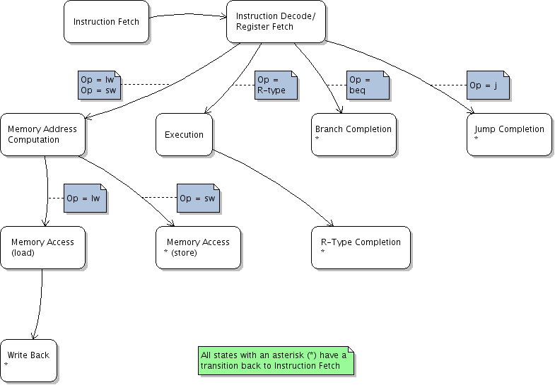
The following diagram shows the control states for a multicycle implementation of part of the MIPS instruction set.
The instruction fetch state performs the instruction fetch activity and part of the PC update activity (PC increment).
For instruction fetch:
For PC increment:
The instruction decode/register fetch state performs the following activities.
The first two items are automatic, requiring no control signals. All of the control signals are involved in branch target computation.
For branch target computation:
At the end of the cycle, the branch target address will be automatically moved into the ALUOut register.
The memory address computation state performs the source operand fetch and ALU operation activity for load and store instructions.
The memory access (load) state performs the memory access activity for load instructions.
The memory access (store) state performs the memory access activity for store instructions.
The memory read completion state performs the register write activity for load instructions.
The execution state performs the ALU operation for non-jump R-type instructions.
The R-type completion state performs the register write activity for non-jump R-type instructions.
The branch completion state performs the ALU operation activity for branch instructions: a subtraction in order to compare the two source operands. Depending on the result of the comparison, the PC may be updated to the branch target address which was computed in the instruction decode/register fetch state.
For comparing the two source operands:
For taking the branch conditionally:
The jump completion state performs the PC update activity for jump instructions.
The following diagram shows how multicycle control circuitry is implemented as a finite state machine. The "next state logic" and "control logic" blocks are combinational logic.
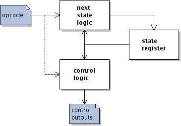
Generally, finite state control can be implemented as either a Moore machine or a Mealy machine.
In a Moore machine, the control signals depend only on the control state. A Moore machine does not use the dashed connection in the figure.
In a Mealy machine, the control signals depend on both the control state and the opcode. A Mealy machine does use the dashed connection in the figure.
The state diagrams for the MIPS multicycle implementation do not include any direct dependence of control signals on the opcode. Thus they are intended for use with a Moore machine. With a Mealy machine, it is possible to bring up some control signals one cycle earlier. This fact could be used to improve the performance of the processor.