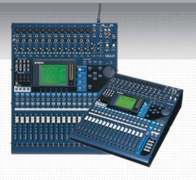
Yamaha O1V96V2
Digital Sound Console
TH 1551
Sound for the Theatre
Lab #8
Introduction to Digital Mixing Consoles and Signal Routing
Yamaha O1V96V2
Digital Sound Console
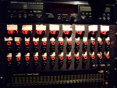
Pin Patch Bay for Line Level Signals and Microphones
Amplifier to Speaker Patch Bay
Purpose:
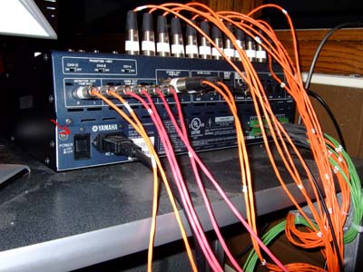
AD - Analog to Digital Converter (XLR and 1/4” inputs on face panel)
ADAT - Optical connection capable of sending 8 channels of 24 bit 96 kHz audio
Word Clock – Synchronizes internal clocks of all devices connected
Slot – Expansion bay on the O1V96V2 (Connects to Layla outputs and Amp EQ inputs)
MIDI – Versatile protocol allowing communications with all other MIDI enabled devices
Layer - Determines what each board fader is assigned to.
Fader Mode – Similar to layers but simulates AUX output knobs with Faders
I/O – Input/Output
Home – Wonderful button that will bring you back to I/O displays
Procedure:
Buttons to push are Italics
Part 1
Part 1 Complete.
Part 2
Part 2 Complete.
Part 3
Purpose: To introduce the Yamaha O1V96v2 Digital board and the function of Scene Memory within the Sound Booth.
Set up for lab:
Note: The following pin patch is needed:
MD (113,114) to AD 1 (169) & AD 2 (170)
CD (111,112) to AD 3 (171) & AD 4 (172)
Omni out (###, ###) to MD in (###, ###)
Note: a patch schedule is taped to the back wall of the Main-stage sound booth
Each person in class will need two different sources.
Each person will need two presets in the Scene Memory starting @ scene #20
Scene memory assignments:
Please use these preset numbers so class projects do not interfere with sound design for Dear Finder.
Liz: 20, 21
Pat: 22, 23
Mariya: 24, 25
Matt: 26, 27
Colin: 28, 29
Nick: 30, 31
Noah: 32, 33
Scott: 34, 35
Useful Vocabulary when using the Yamaha O1V96v2:
AD- Analog to Digital Converter inputs (12 XLR and 16 1/4” inputs on )
ADAT - Optical connection capable of sending 8 channels of 24 bit 96 kHz audio
Word Clock – Synchronizes internal clocks (Sample rate) of all devices connected
Slot – Back expansion bay on the O1V96V2 (Connects to Layla outputs and Amp EQ inputs)
MIDI – Versatile protocol allowing communications with all other MIDI enabled devices
Layer - Determines what the faders are assigned to.
Fader Mode – Similar to layers but simulates AUX output knobs with the 16 Faders
I/O – Input/Output
Home – Wonderful button that will bring you back to I/O Meters in display
Scene- Saved board settings that can be recalled
Useful info:
The input procedures for a digital board are no different from an analog board. The functions of Gain and Pad all operate as if on an analogue board. All other functions from an analog board can be found in a condensed version on the O1V96v2. For example, there is only one area to access the digital equalizer settings for all 32 inputs and 16 outputs. The Select button above each channel determines what channel will be affected.
Troubleshooting
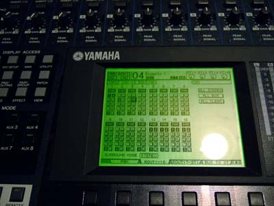
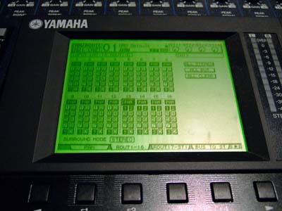
The key for troubleshooting on a digital board is being able to follow signal flow. A basic signal routing display can be found by repeatedly pressing the Home button. While the display can seem cryptic it can show internal components that would normally be multiple send/return devices for an analog board. Use the Home meter display to see how far signal is progressing through the board. The output display can be found by switching layers while in the home screen.
Words in Italics are buttons to push.
Procedure
Part 4 Setting Input Levels and Recording a Scene
1. Turn on the Yamaha O1V96v2 by pressing the power button on the back of the board.
Yamaha Power Switch Location
2. Select the Scene Memory # 1 “UMD Default by using the arrows in the Scene Memory box above the selector wheel.
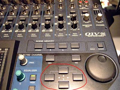
Scene Box Selector Arrows
3. Push Recall to load the scene. A message should flash that the scene has been loaded.
Note: If the scene shows Ud instead of a number, Press Recall to restore the last loaded scene.
4. Push Layer 1-16 to select input channels 1-16. The green light indicates it is selected.
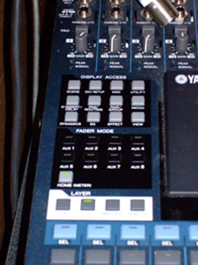
Yamaha Digital Sound Console
Faders
5. Push ON on inputs 1-4.
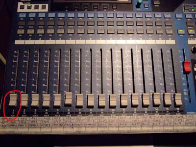
Yamaha Faders
(Masking tape information describes what each fader does depending on which layer you're in.)
6. Press play on both sources.
7. Use Pad and trim to prevent clipping (the red Peak light by the inputs).
8. Set good listening levels.
Note: The STEREO fader on the right of the faders controls the volume of the booth monitors. Please set accordingly, will be saved into the project scenes.
9. Save these settings as a scene by selecting a scene with No Data flashing.
10. Press STORE.
11. Use the Arrows and Enter to input Name #:1.
12. Use DEL to remove extra letters.
13. Select OK to save scene.
14. Push SEL above fader 1 and use the PAN knob to pan the signal all the way left.
15. Push SEL above fader 2 and use the PAN knob to pan the signal all the way right.
16. Repeat steps 14 and 15 for faders 3 and 4 respectively.
17. Resave scene by pressing STORE and selecting OK with Enter.
18. Press Home button to return to meter screen.
1. Take out faders 2 and 3, increase level of inputs AD 1 and AD 4 by 5 dB.
2. Save as Scene Name #:2
3. Press SCENE under DISPLAY ACCESS to the left of the display twice until input fade time is showing.
4. Select 1 with the ARROWS and use the selector wheel to set it to a fade time.
5. Repeat step 22 for 2-4. Make them all different times under 30 Seconds (max of the fade).
6. Re-save the scene as Name #:2.
1. Recall scene Name #1
2. Restart audio sources
3. Recall scene Name #2
4. Enjoy!
End of lab.
SHUTDOWN PROCEDURE
1. Recall scene “UMD Default”
2. Turn of amp
3. Turn off board
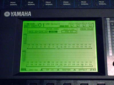
Yamaha Home Screen
Yamaha Scene Save