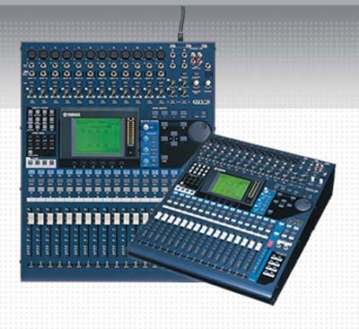
Yamaha O1V96V2
Digital Sound Console
TH 1551
Sound for the Theatre
Lab #9
Introduction to Signal Processing
Yamaha O1V96V2
Digital Sound Console
Purpose: To introduce recording and signal processing with the Yamaha 01V96v2 digital control console.
Set up for lab:
Note: The following pin patch is needed:
MD (113,114) or CD (111,112) to AD 1 (169) & AD 2 (170)
Omni out 1 and 2 (189, 190) to MD in L & R (115, 116)
Note: A patch schedule is taped to the back wall of the Main-stage sound booth with patch information for other devices and outputs.
New Vocabulary
Aux - Additional line level output used for a myriad of tasks
Bus - Output signal sent to amplifiers
Softpatch - Using software to direct and control signal flow
PFL - (Pre Fade Level) signal is bypassing fader
Dry - pure unadulterated signal
Wet - altered signal
Troubleshooting
The key for troubleshooting on a digital console is being able to follow signal flow. A basic signal routing display can be found by repeatedly pressing the Home button. While the display can seem cryptic, it can show internal components that would normally be multiple send/return devices for an analog board. Use the Home meter display to see how far signal is progressing through the console. The output display can be found by switching layers while in the home screen.
Procedure
Words in Italics are buttons to push.
Part 1 Setting input levels
Note: If the scene shows Ud instead of a number, Press Recall to restore the last loaded scene.
Note: The STEREO fader on the right of the faders controls the volume of the booth monitors.
Part 2 Sending Signal to all 4 onboard effects processors
Note: Aux 5-8 are set up as PFL and are not affected by input fader level.
Play your source and check that faders 1&2, and 13-16 are registering signal.
SHUTDOWN PROCEDURE