ECE
2212
EXPERIMENT
9
29
March 2018
Bipolar
Junction Transistor (BJT) Common-Emitter Amplifier
Note 1: EXTRA CREDIT OPPORTUNITY #1:
Up to 30 Points added to your
end-of-the-semester Quiz Point Total. How do you earn this? I want
circuit diagrams and specifications for power amplifiers and
related equipment that you may have for some of your “stuff” and is usable,
that is, supports in-class discussions when we get to power amplifiers
towards the end of the semester. Information such as circuit diagrams,
specifications for your sound systems, guitar
amps, car stereos, powered sub-woofers, associated power supplies, speaker
systems, etc. I define power loosely in that information on your portable
electronics such as iPODs,mp3 players, smart
phones, tablets, etc. also is interesting to me and appropriate for class
discussion. Homebrew projects in these categories are appropriate. I would like to borrow the material to
supplement our class discussions on power amplifier circuits. Do not just
go to the WEB for information that doesn’t relate directly to stuff you
or your parents have. Hard Deadline for receipt of materials is in
class on Monday, 9 April. Earlier is better!
Be sure your name is in the submitted materials. They will be
returned. I will award up to 30 points based upon relevance and
class usability and you describing the item and technical information orally to the class. Feel free if to show
me what you have if you have questions.The meaner and
badder stuff, the better.
Feel free to ask if you have any questions.
Note 2: EXTRA
CREDIT OPPORTUNITY #2:
There two additional candidates for a new tenure-track Assistant
Professor in the power/energy/power electronics area. They will be interviewing on Friday, 30
March and Friday 6 April. Each candidate will be presenting a seminar
(times to be determined) and also meetings (tentative) with students. It is important to have student participation
in this interview process. I will award 5
Points for each seminar and student meeting that you
attend which totals between 30 and 40 Points. After each participation event, send me an
e-mail that you attended since I may not actually remember if you were
there. I will say more about schedules
as I know more.
Note 3: Experiment 9 and Experiment 8 reports will be
due Thursday 5 April. This will allow
those of you who didn’t complete Experiment 8 because of a faculty candidate
visit to complete Experiment 8.
COMPONENTS
2N3904 or 2N2222 npn transistor
Resistors: 5kW, 100kW,
others as needed.
Capacitors: 1 or 10 microfarad
as needed.
Note: Use the 2N3904 or 2N2222 npn transistor device models in SPICE rather than the
default model
DC Bias Analysis
Construct the circuit in Figure 9.1. Use VCC
= 10 volts. Adjust R3 such that your Q-Point for VCEQ and ICQ are in the center third of the
DC Load Line. Measure Q-Point values
for IBQ, VCEQ, and ICQ. Be sure you
measure the actual resistor values for your measurement to obtain more accurate
results. Compare your results with a
SPICE analysis of this circuit. Vs
should be turned off for the DC analysis.
This DC circuit is similar to the circuit in Experiment 8. Watch the polarities on the electrolytic
capacitors. Positive terminal to the
base and the other positive terminal to the collector.
Note that your SPICE Output File includes
Q-Point values as well as small-signal model parameters.
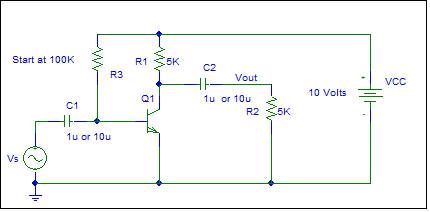
Figure 9.1
Amplifier Operation
Now measure the voltage gain defined by Av=vout/vs. Use a 1 kHz
sinusoidal input for Vs and change the amplitude as necessary to obtain a
sinusoidal voltage output. Also look at
the transfer characteristic. Compare
with a SPICE analysis. The voltage gain
is computed from Av = -gm(Rc||RL)
and gm=ICQ/VT where VT = kT/q approximately 25.8 mV
at 300K.
Statistics is a required course.
TESLA Model 3?
The iPhone is better!
Another LED cartoon for your enjoyment