EE 2212
PROBLEM SET 5
S. G. Burns
Due:
Wednesday, 28 October 2020
NOTE 1: I strongly encourage
studying the photonic concepts and
devices from the (Photonics PowerPoint).
Problems associated with Text Section 3.18 are quite limited but the optoelectronics
area is of rapidly growing importance.
You can expect Quiz 5 to cover topics in the Text Section 3.18 and the
Photonics PPT slides PhotonicsSupplementTextSection3.18.ppt
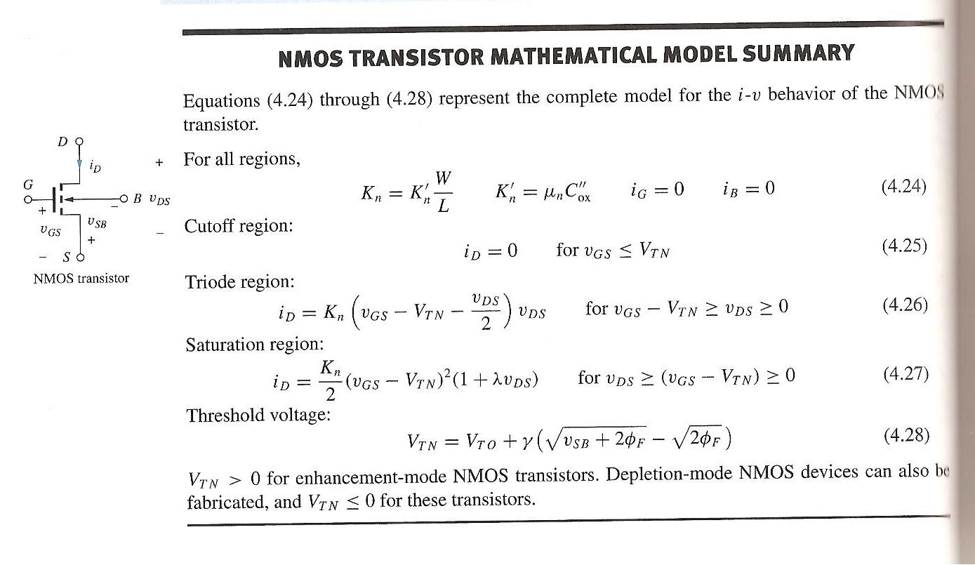
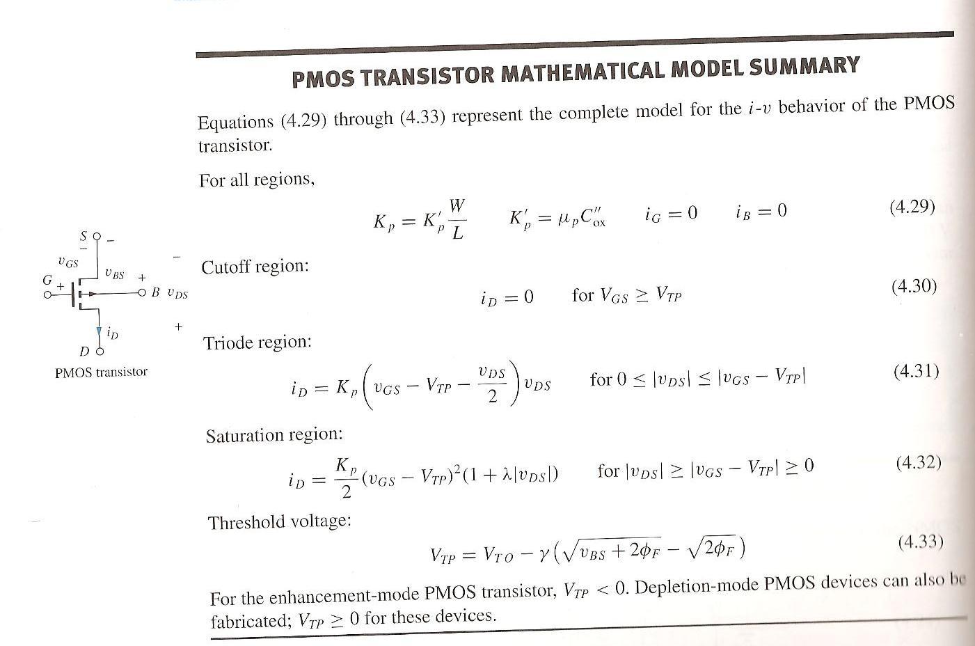
NOTE 2: Table 4.6 on Page 203 provides useful generic FET
specifications information. If these data are not provided in any of the Chapter 4 text problems, use
information in Table 4.6. Also the
inside of the front cover has
all sorts of useful data. Just
below Table 4.6 on Page 203, you will
also find some key constants;
also on the inside of the front cover.
NOTE 3: I also want to call your attention to the following
link from our WEB page
FETNMOSSummary.jpeg and FETPMOSSummary.jpeg
NOTE 4: Be sure your WEB browser
displays symbol font correctly.
NOTE 5: Problems 5 and 6 relate to introductory FET
topics. They are plug-and chug.
Problem
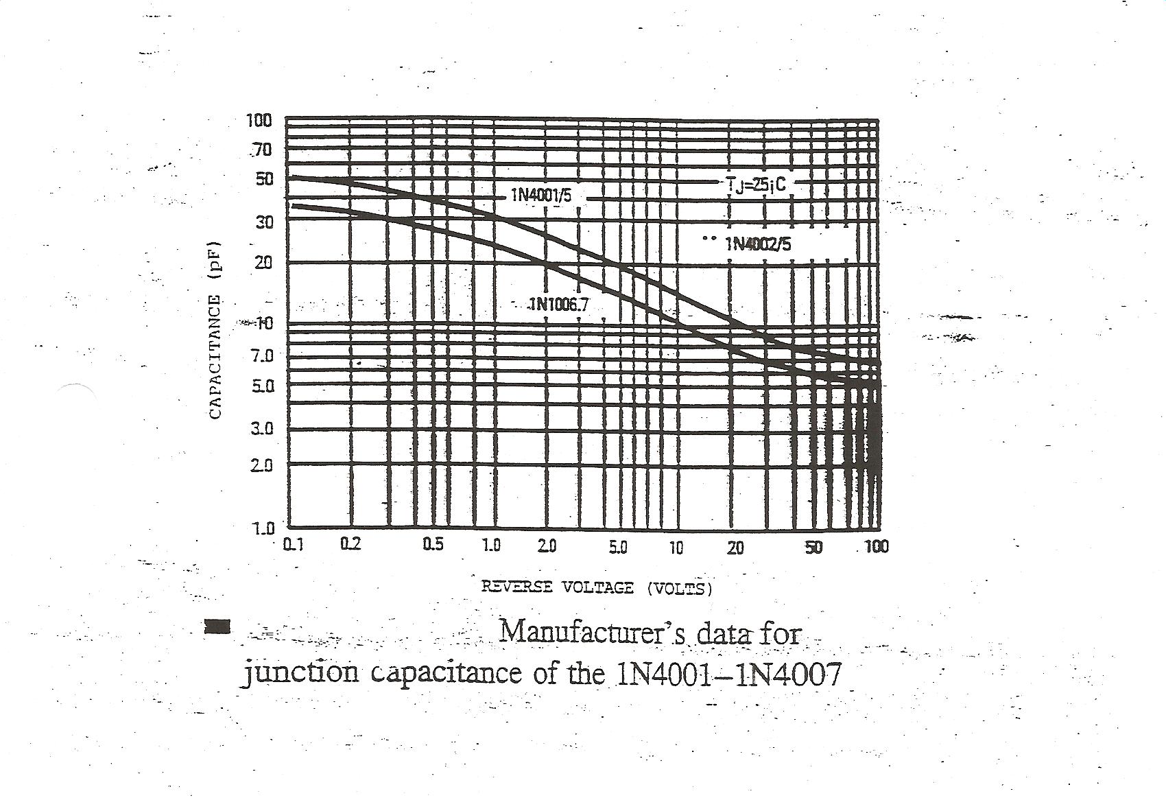
1 Tuned Circuit Design Using A VARICAP
(a) Refer to the capacitance curves for the
Motorola 1N4002 1N400XCap.JPG . The input
tuning circuit of a standard analog
FM radio is given below.
Specify, that is design for, a voltage, capacitance required to tune the circuit to the center
frequency of KUMD-FM which operates at 103.3 MHz. (By the way-Did you know that KUMD is
probably going to be sold to WDSE-Local PBS Station). Under Minnesota Board of Regents
consideration. Sketching and
labeling a representative resonance curve is required to support your
calculations.
(b)
Repeat if you use the Motorola MMBV109LT1 MV209. Refer to the EE 2212 WEB pages Hyperdiode1.JPG and HyperDiode2.JPG.
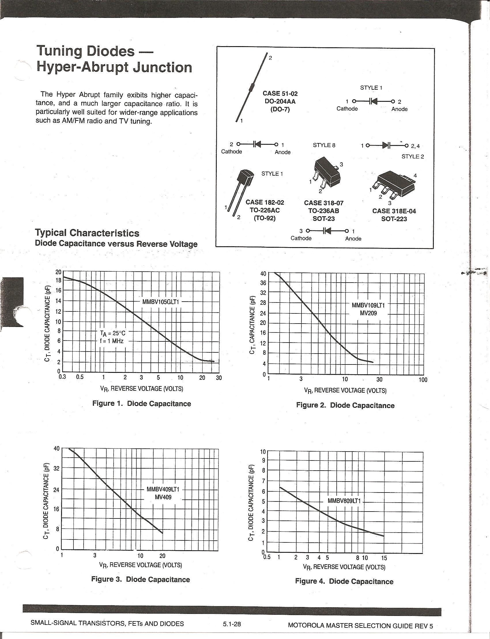
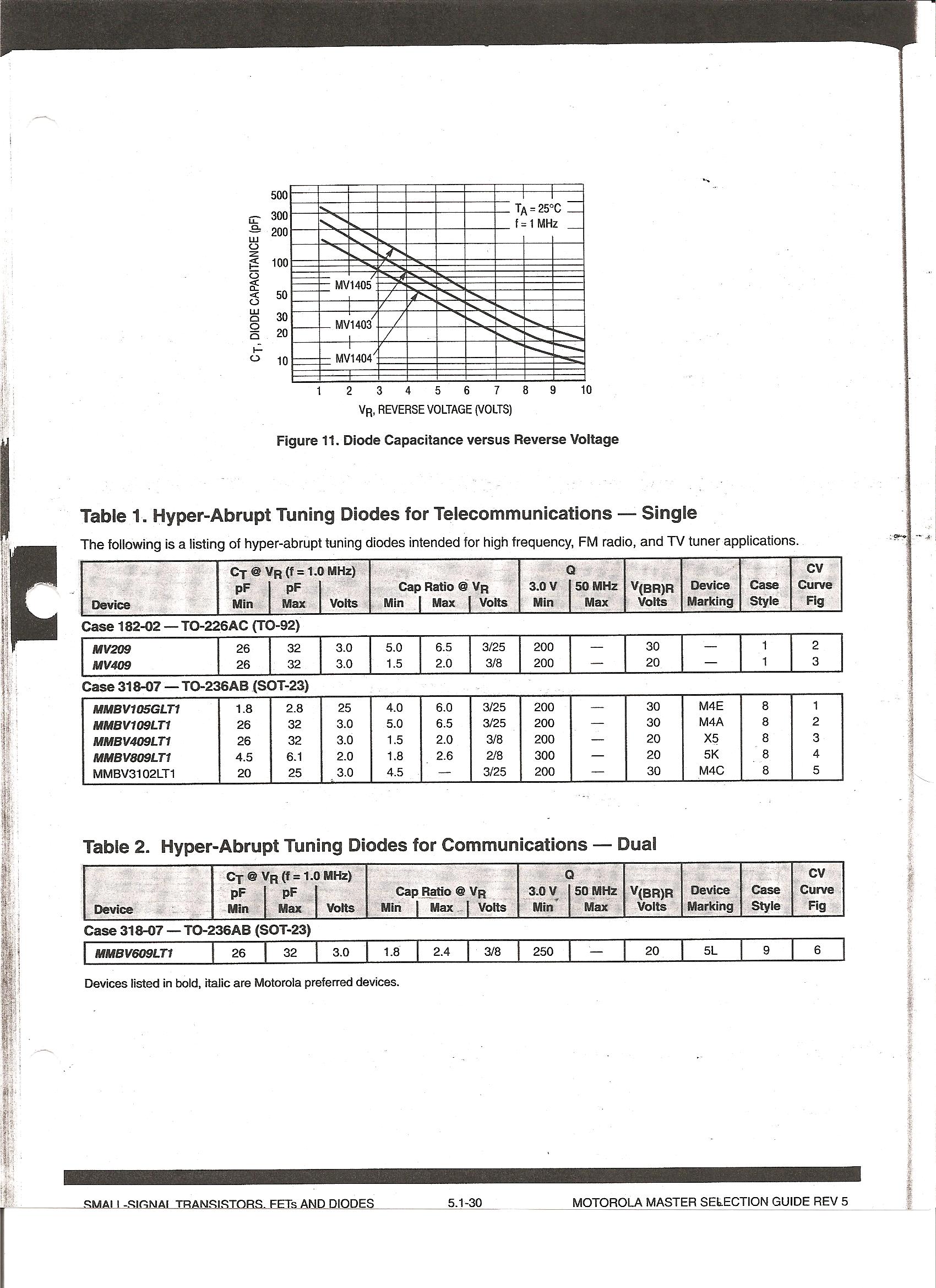
_files/image003.gif)
Problem 2 (Excerpted from an old quiz) Assume VJ = 0.7 volts.
(a) Using the derating curve from the 1N4001 shown
below, compute the total thermal resistance, q.
(b) Recommend a maximum operating current and power if this power
diode were located under the hood of your car where the temperature approaches
212°F = 100°C.
_files/image005.jpg)
Problem
3
Text 3.121 and 3.122 as a combination.
A bit of a plug-and-chug. You
will find PeriodicTableTextChapter2.jpeg useful for the EG values. This is a useful review of Problem 4 on
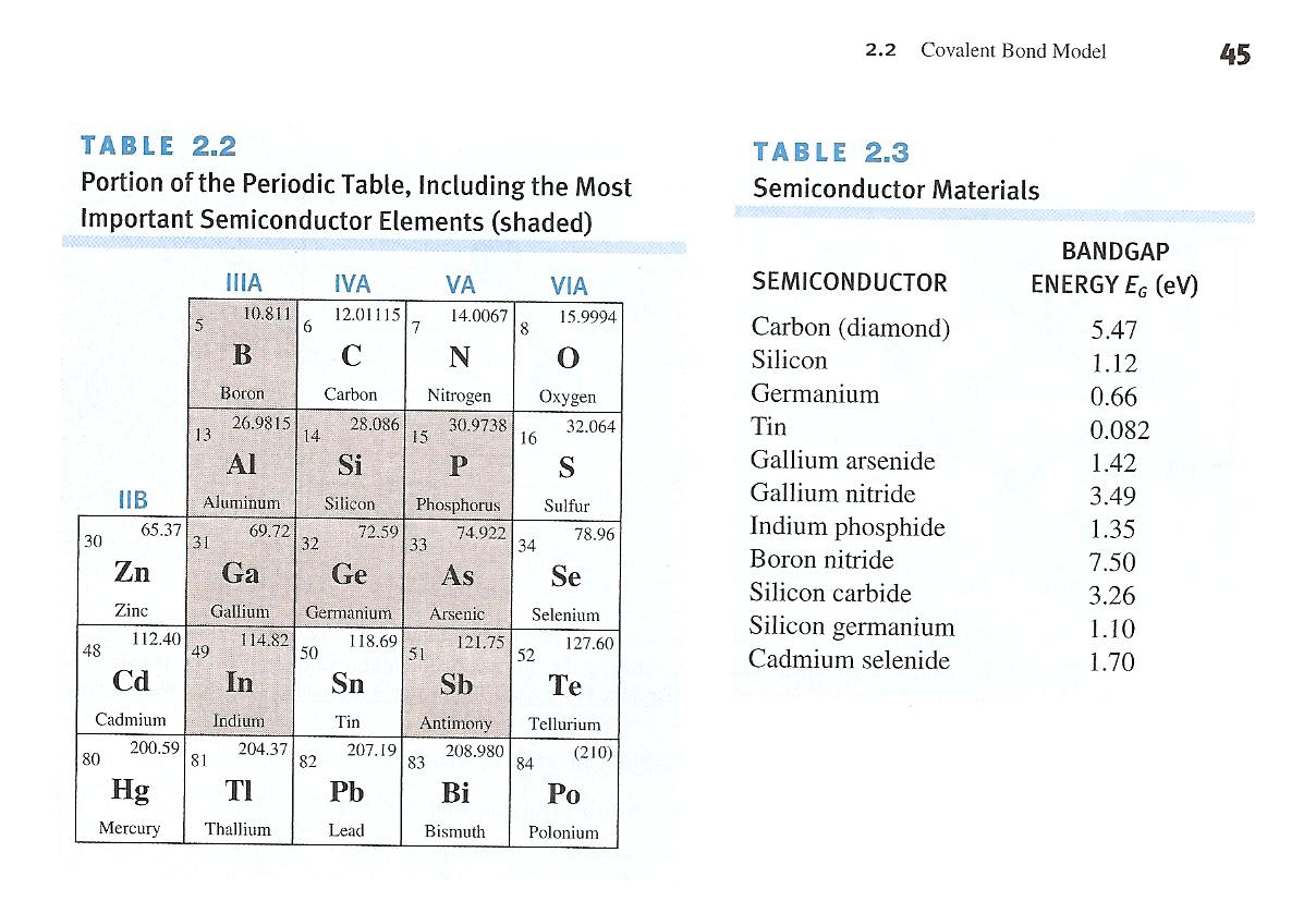
Problem Set 3.
Provide your answers in a table, of a form shown below, to
summarize your calculations.
|
Material |
Eg |
Wavelength λ in
μm |
Relation to Visible
Spectrum |
|
|
|
|
|
|
|
|
|
|
Problem 4 Solar Panel Analysis (Adapted from an old
quiz). Refer to topics covered in the
PhotonicsSupplementTextSection3.18.ppt . This
commercial solar panel has an area of 1.6 m2. The I-V curves are shown below. Estimate/compute
values for the quantities indicated. Illustrate your answers on the vendor I-V curves.
(a)
_____________Reasonable accepted value for
the solar constant above the Earth’s atmosphere.
(b)
_____________Reasonable accepted value for
the solar constant at the surface of the
Earth.
(c)
At the Earth’s surface, the solar spectrum
peaks in the (IR, Red, Green-Yellow,
Blue, UV).
(d)
______ Open Circuit Voltage, VOC.
(e)
______Short Circuit Current, ISC
(f)
_______Estimate of maximum Power Output
corresponding to your answer in Part (b) above
and illustrate, on the graph,
how you obtained this value.
(g)
________________ Panel Conversion Efficiency, %, using your
results from Part (f) above.
Panel Area = 1.6 m2
_files/image007.jpg)
_files/image009.gif)
Problem 5 Text Problem 4.1 (Look at Figure 4.2 for
guidance) and Text Problem 4.2 as a
combination. For Text 4.2 observe that
this is Cox, capacitance per unit area. Watch your units. Usually farads/cm2
are preferred for the capacitance per unit area units. When the text and in the
industry talks about an MOS capacitor, they are usually referring to
capacitance/unit area. The total capacitance can then be scaled by multiplying
by (W x L). Refer to Monday, 24 February class
notes. This idea of scaling is a very
important VLSI design concept. The
parallel plate basic capacitor model works well! We will also soon observe how this plays into
imaging and display applications.
Problem 6
Text 4.4 and 4.8 for NMOS and Text 4.47 for PMOS. Some additional basic calculations to provide
experience in units and nomenclature.
Organize your results in a table.
Page 160 (NMOS) and 161 (PMOS) has a table defining the relationships
for key FET model parameters. Refer to
the WEB links in Note 2.
All
of these cartoons are relevant my pre-COVID life at UMD.
(1) I have my own K-Cup coffee pot to avoid
issues.
(2) I have a slide rule collection and even know
how to use them. Amaze your parents and
grandparents-Stop in to my office when face-to-face resiumes post-COVID if you want a short course on how to use a slide rule. Free lessons! In their day, prior to the early 70s, slide
rules were a great tool to learn about log10 theory and
applications. I have a few displayed in
my office. My HP 35 scientific
calculator I purchased as a poor graduate student was $400. Lots of Ramen noodles for a couple of months
but I had to have it!
(3) The iPAD and Macbook are so friendly and the
graphics are great, but I can’t find a good SPICE APP.
(4) For those of you who are aware of the current
UMD budget issues, the Dilbert cartoon says it all. ENJOY!
_files/image010.jpg)
_files/image012.jpg)
Recall
the WOM (Write-Only-Memory) Signetics Data Sheet from the attachment to the
diode circuits experiment. Fun-loving
(sort of depends on you define fun)
Signetics engineers may have
taken a clue from some engineers at EIMAC or the other way around. EIMAC
manufactures high power and specialty vacuum tubes used in high power
transmitters and RF generators and related. This is a data sheet for the
“PHANTASATRON”. EIMAC is now a subsidiary of Communications and Power
Industries. Even though small vacuum
tubes are no longer made in the U.S., some manufacturers in Russia and Brazil
cater to the high end audiophile market.
We will talk about vacuum tube audio amplifiers towards the end of the
semester. Larger, high power
transmitting tubes and speciality vacuum tubes are manufactured by EIMAC and
others. Enjoy!
_files/image014.gif)
_files/image016.gif)