ECE
2212
PROBLEM
SET 7
S.
G. Burns
Due: Wednesday, 30 October 2013
Problems 1 and 2 are “plug
and chug” to help you familiarize yourself with the numbers.
1. Text
Problems 4.1 and 4.2 and for 4.2, observe that this is Cox, capacitance per
unit area. Watch your units. Usually capacitance/cm2 are preferred for the area reference. When the text and in
the industry talks about an MOS capacitor, they are usually referring to
capacitance/unit area. The total capacitance can then be scaled by the W x L
product. The parallel plate basic capacitor model works well!
2. Text
4.4 and 4.8 for NMOS and Text 4.48 for PMOS. Organize your results in a table.
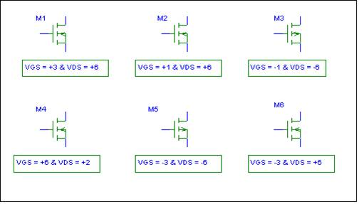
3. For
the indicated bias conditions, state whether the FET is operating in the OHMIC
(TRIODE) region, SATURATION region, or CUTOFF region. Explain your reasoning. Assume
that |VT | = 2
volts for both the NMOS and PMOS enhancement mode transistors.
M1
__________ M2 __________ M3 __________
M4 __________ M5
__________ M6 __________
4. Refer to the sketch of
an n-channel enhancement-mode MOSFET fabricated in silicon. Assume room
temperature operation. Also
assume l = 0. Units are important
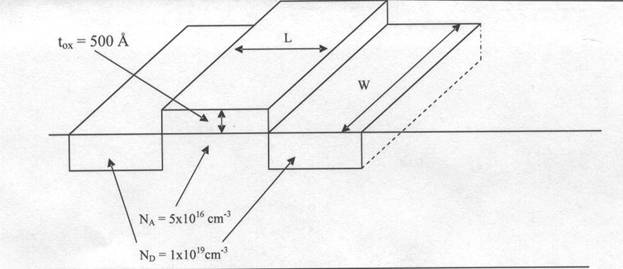
![]()
(a)
Compute
a value for Cox .
(b)
Compute
a value for the threshold voltage, Vt
using the threshold voltage graph posted on the WEB page.
(c)
Assume
W/L = 10 and make reasonable assumptions and/or use values from Table 4.6 for
any other physical parameters you may need. Compute values for “k” and “KP” and
then use your results from this part and Parts (a) and (b) to generate a Sichmann-Hodges Level 1 model equation.
(d)
Using
your calculated results from Part (c), sketch and numerically label the iD versus vDS
as a function of VGS curves. Label the Saturation, Cutoff, and Ohmic (Triode) regions.
5. Text 4.18 NMOS . In addition, refer to Text Figure P4.18
associated with Text Problem 4.18.
Using the SPICE example demonstrated in class on Monday 21 October, generate a SPICE simulation by modifying the
default NMOS transistor that will match
the curves in P4.18 figure. Also note
that extracting MOS parameters from the graphical output has been used on old
quiz problems.
6. Text 4.49 PMOS In addition, refer to Text Figure
P4.49 associated with Text Problem 4.18. Using the SPICE example I demonstrated in
class on Monday, 21
October, generate a SPICE simulation by modifying the default NMOS
transistor that will match the curves in
P4.49 figure. Also note that extracting
MOS parameters from the graphical output has been used on old Quiz problems. Note that rigorously, the PMOS curves in this
figure should be in the 3rd quadrant
All
of these cartoons are relevant my life at UMD.
(1) I have my own coffee pot.
(2) I have a slide rule collection and even know
how to use them. Let me know if you want
a short course.
(3) The iPAD and Macbook are so friendly but I can’t find a good CADENCE
SPICE App.
(4) Finding enough $ to do it all is always an
issue.
ENJOY!