ECE 2212
PROBLEM SET 2
S. G. Burns
Due: 6 February 2013
Unless otherwise stated, assume all operational
amplifiers are ideal. Therefore you can use the summing point constraints.
1.
Text 1.37 Straightforward summing amplifier
“plug and chug”.
2.
Text Problem 1.42 and consider the following
design issue. Suppose I wanted to continue this approach
to the design of an 8-bit DAC (Digital-to-Analog Converter). Is this circuit design approach a good
idea? Why or why not? To guide you in your answer, consider the
resistor ratios and resistor accuracy required of these ratios for achieving an
accurate 8-bit DAC.
3.
Figures P12.3, P12.9,
12.14, and P12.17 (pages
774 and 775) are cascaded operational amplifier circuits. Compute the voltage gain, ![]() = vO/vI
for each circuit. When you use summing
point constraints and the circuit topologies we have discussed in class, the
voltage gain computation for each circuit can be done in ONE line!
= vO/vI
for each circuit. When you use summing
point constraints and the circuit topologies we have discussed in class, the
voltage gain computation for each circuit can be done in ONE line!
4.
From An Old Quiz
Design an
audio equalizer/mixer circuit using a
μA741 operational amplifier.
Apply the following input signals.
Input
Signals:
Design
criteria:
v1(t) must
have a voltage gain of 26 dB
v2(t) must
have a voltage gain of 12 dB
v3(t) must
have a voltage gain of 20 dB
Your design
must include:
·
Detailed and well-labeled circuit diagram.
·
A set of self-consistent values for all four resistors with
design justification. Resistor values
must be compatible with μA741.
·
An equation for the resultant output
voltage, vo(t). Phase is
important!
·
The frequency in Hz for each of the three
input signals.
·
Are these three signals within the normal
human hearing range? Explain.
5.
Now that you have provided a
solution, use the same approach to design the electronics for an electric
guitar.
![MCj04079760000[1]](ProblemSet2_files/image025.gif) There are six strings on a standard electric guitar and their
frequency and musical note
relationships are shown in the table. Each of the magnetic pickups for the six strings
will be modeled as six signal sources v1(t), v2(t), v3(t),
v4(t), v5(t), and v6(t). DESIGN an operational amplifier system
(guitar preamp/audio equalizer ) such that the resultant output, which you
would listen as the sum, meets
the individual string amplitude specifications given in Row 4 of the
table. The figure associated with Text Problem
1.41 provides excellent guidance.
There are six strings on a standard electric guitar and their
frequency and musical note
relationships are shown in the table. Each of the magnetic pickups for the six strings
will be modeled as six signal sources v1(t), v2(t), v3(t),
v4(t), v5(t), and v6(t). DESIGN an operational amplifier system
(guitar preamp/audio equalizer ) such that the resultant output, which you
would listen as the sum, meets
the individual string amplitude specifications given in Row 4 of the
table. The figure associated with Text Problem
1.41 provides excellent guidance.
Assume ideal
operational amplifiers, however resistor values must be compatible with a mA 741, that
is all resistors > 2kW. Your design must include a detailed,
well-labeled circuit diagram.
|
String 1 High E |
String 2 B |
String 3
G |
String 4
D |
String 5
A |
String 6
Low E |
|
v1(t) |
v2(t) |
v3(t) |
v4(t) |
v5(t) |
v6(t) |
|
f1 > |
f2 > |
f3 > |
f4 > |
f5 > |
f6 |
|
10 dB |
20 dB |
-6 dB |
3 dB |
14 dB |
30 dB Nice bass boost |
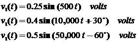
6. Non-linear
elements are quite common as we will observe later this semester. One
non-linear element is called an analog multiplier. The terminal characteristics
of the analog multiplier are defined as shown in the figure.
Show that this circuit can be used an analog signal divider. That
is derive Vo in terms of Vs1 and Vs2.
![]() These cartoons obtained from a friend raiding a secret stash
at a well known laboratory instrument company.
These cartoons obtained from a friend raiding a secret stash
at a well known laboratory instrument company.


And more from my file of stuff:
General wisdom of the
ages because if I am not a fan of the continual requests to update something or
other in Windows