EE
2212
EXPERIMENT
8
23
March 2017
Bipolar Junction
Transistor (BJT) Measurements, Circuit Analysis, and Amplifier Operation
Report
Due: Thursday, 30 March 2017
NOTE 1: We may not have enough background from
Wednesday’s class but I will continue the discussion at the beginning of our
lab meeting.
COMPONENTS
2N3904 or 2N2222 npn transistor
Resistors: 5 kΩ and 100 kΩ
Note: Use the 2N3904 or 2N2222 npn transistor device models in
SPICE rather than the default model. It
will be a better match against which to compare your experimental results.
DC Bias Analysis
Construct the circuit in Figure 8.1. Use =
10 Volts for the DC supply. Measure and record the Q-Point values of IB,
IC, VBE, and VCE. Measure the voltage across the RB and RC
resistors to obtain the base and collector current rather than inserting an
ammeter in series. I suggest this
approach since the internal fuse in the multimeter is
difficult to replace. Be sure you measure the actual resistor values for your
measurement to obtain more accurate results.
Compare your results with a SPICE analysis of this circuit. Use the 2N3904
or 2N2222 in the SPICE library. The
signal source vin(t) should be set to zero
for this portion of the experiment. You
probably will need have to adjust VBB from the nominal 1.5 volts and
perhaps also the value of the 100 kΩ resistor to obtain a Q-Point in the center third of
the load line, forward-active region, because of the probable wide variation of
BJT β values that are in the bin.
You can use a potentiometer to adjust RB also. Observe that you can use the signal generator
to provide both the VBB and vin(t)
by providing an offset to vin(t).
Also note that SPIC will give you the dc bias
point voltage and current values. I will
demonstrate this.
Demonstrate
Small-Signal and Large-Signal Operation
Now set vin(t) for a 1 kHz sine wave from the function
generator. Do not change the VBB,
that is keep the same dc offset for the Q-Point. Adjust the amplitude initially to 0.5 Volts
(1 VPeak-to-Peak), Measure the
voltage gain defined by vout/vin. Simulate the circuit in SPICE with your
transistor using a transient analysis.
Note that SPICE also provides key Q-Point values for small-signal
parameters as discussed in Wednesday’s class.
Explain your results in the context of a load-line analysis. Use the small-signal model to compute the
voltage gain. Also show the transfer
characteristic. Adjust vin(t) to demonstrate
clipping in both the saturation and cutoff portions of the load line. Note that saturation in a BJT is defined
significantly different than for a FET!
However clipping is still clipping whether a FET or BJT circuit.
Reminder that both VBB and RB may need to be
adjusted to obtain the Q-Point in the center third of the load line depending
upon your actual BJT specifications.
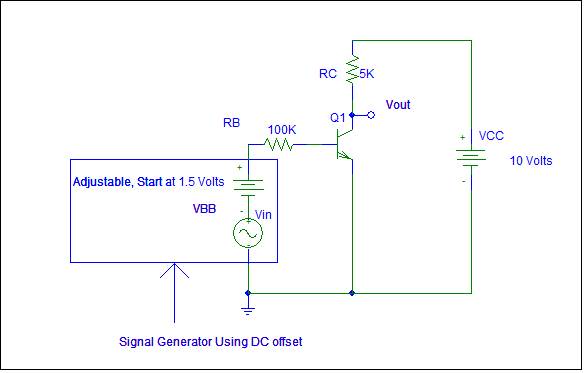
FIGURE 8.1 BJT Circuit
More Stuff From My Files of Good Stuff

Actually, I wasn’t too excited
about Apple’s new iPhone 7 release and now the Google phone is out but I am
waiting for the iPhone 8.

Another
classic math joke if can handle it!

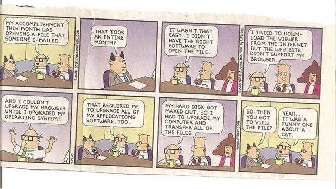
My desktop computer uses WINDOWS 8 and the Dilbert
cartoon expresses my feelings about software upgrades! I guess WINDOWS 10 in my HP laptop (Microsoft
is skipping WINDOWS 9) is supposedly better.
The popups are a pain. Time will
tell. I also feel the same way about the
MyU portal.