ECE
2212
EXPERIMENT
9
30
March 2017
Bipolar
Junction Transistor (BJT) Common-Emitter Amplifier
COMPONENTS
2N3904 or 2N2222 npn transistor
Resistors: 5kW, 100kW,
others as needed.
Capacitors: 1 or 10 microfarad
as needed.
Note: Use the 2N3904 or 2N2222 npn transistor device models in SPICE rather than the
default model
DC Bias Analysis
Construct the circuit in Figure 9.1. Use VCC
= 10 volts. Adjust R3 such that your Q-Point for VCEQ and ICQ are in the center third of the
DC Load Line. Measure Q-Point values
for IBQ, VCEQ, and ICQ. Be sure you
measure the actual resistor values for your measurement to obtain more accurate
results. Compare your results with a
SPICE analysis of this circuit. Vs
should be turned off for the DC analysis.
This DC circuit is similar to the circuit in Experiment 8. Watch the polarities on the electrolytic
capacitors. Positive terminal to the base
and the other positive terminal to the collector.
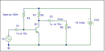
Figure 9.1
Amplifier Operation
Now measure the voltage gain defined by Av=vout/vs. Use a 1 kHz
sinusoidal input for Vs and change the amplitude as necessary to obtain a
sinusoidal voltage output. Also look at
the transfer characteristic. Compare
with a SPICE analysis. The voltage gain
is computed from Av = -gm(Rc||RL)
and gm=ICQ/VT where VT = kT/q approximately 25.8 mV
at 300K.