EE 2212
PROBLEM SET 10
1.
The
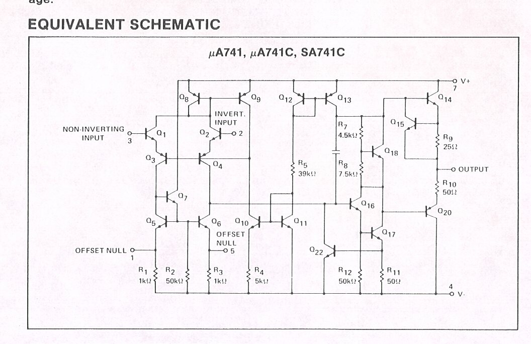
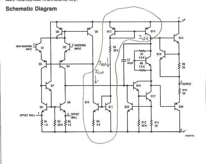
following is a circuit diagram of a National Semiconductor LM 741 operational
amplifier. Recall from the beginning of the semester that I mentioned that you
will be able to analyze key sub-circuits of operational amplifiers and related
circuits by the end of the semester. I
have circled key elements of the current source system you are analyze in the
LM 741. Assume all |VBE(on)| =
0.7 volts (for both npn and pnp).
V+ = 12 volts and V- = -12 volts. All npn transistors have equal junction areas and all pnp transistors have equal junction areas. 741signetics.jpg
You will have to solve a transcendental
equation to obtain IC10.
Compute
values for IREF, IC10, and I13.
2. Text 15.1 BJT Differential
Pair
3. Text 15.4 BJT Differential Pair Similar to Text 15.1
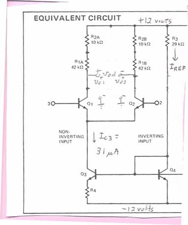
4. Modified from an old quiz. Refer to the modified and annotated partial
diagram of a Fairchild μA725 operational amplifier integrated
circuit. Assume all npn BJTS are matched
with β = 150 and an Early voltage of VA = 100 volts. IC3 = 31 μA. The circuit is connected to ± 12 volt
power supplies. Compute the following
quantities for this circuit (Observe, you will have to compute a value for R4):
(a) The differential mode voltage gain, Adm.
(b) The common-mode current gain, Acm.
(c)
Common-mode
rejection ratio, CMRR, numerically and in dB.
You may be asked to do this
over Summer Break

Minnesota Vikings Draft
Pick. Go Packers

Volunteering Always Looks
Good On Your Resume. Be sure you register
with GoldPass on the UMD Career and Internship WEB
Site