EE
2212
PROBLEM
SET 2
S.
G. Burns
Due:
Wednesday, 1 February 2017
Note
1: Again, a reminder that
some of the WEB browsers such as Firefox and shareware versions of Internet Explorer and Chrome and its derivatives may not display or print SYMBOL and ADOBE
fonts correctly. There are also some
issues with iOS. Also, shareware
versions of WORD and WORD without the embedded symbol font may also have issues in
this regard. For example, 1 kW should
show as k followed by Greek upper case omega. If it displays or prints as 1 kW you have an
issue with all Greek symbols! This could lead to errors with units since micro ”μ” will read as “m” and so forth which yields an
error of 109!!! Be careful.
Note 2: Unless otherwise stated, assume all
operational amplifiers are ideal. Therefore you should use the summing point constraints to
significantly minimize algebraic complexity.
1.
Figures P12.3, P12.5,
P12.6, P12.9, 12.14, and P12.17 (pages 759 and 760) are cascaded
operational amplifier circuits. Compute
the voltage gain, ![]() = vO/vI
for each circuit. Believe it or not,
when you use summing point constraints and the circuit topologies we discussed
in class Monday and Wednesday of this week, the voltage gain computation for each
circuit can be done in ONE line! Also for added
practice, compute the voltage gain in dB for each circuit.
= vO/vI
for each circuit. Believe it or not,
when you use summing point constraints and the circuit topologies we discussed
in class Monday and Wednesday of this week, the voltage gain computation for each
circuit can be done in ONE line! Also for added
practice, compute the voltage gain in dB for each circuit.
2.
Adapted from an old
quiz. A 4-Bit DAC
circuit is given. Text 1.42 is
useful as guidance to work this problem.
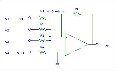
Refer to the graphs for V1,
V2, V3, and V4.Assume the digital pulse amplitudes are all 1 volt.
(a) Specify a set of self-consistent values for
R2, R3, R4, and Rf. Note that R1 = 16 kW.
(b) Sketch and label the DAC output voltage, Vout, on the set of axes provided.
(c) Consider the following design issue. Suppose I wanted to continue this approach to the design of an
8-bit DAC
(Digital-to-Analog
Converter). Is this circuit design
approach a good idea? Why or why
not? To guide you in your
answer, consider the resistor ratios and
resistor accuracy required of these ratios for achieving an accurate 8-bit DAC. t
t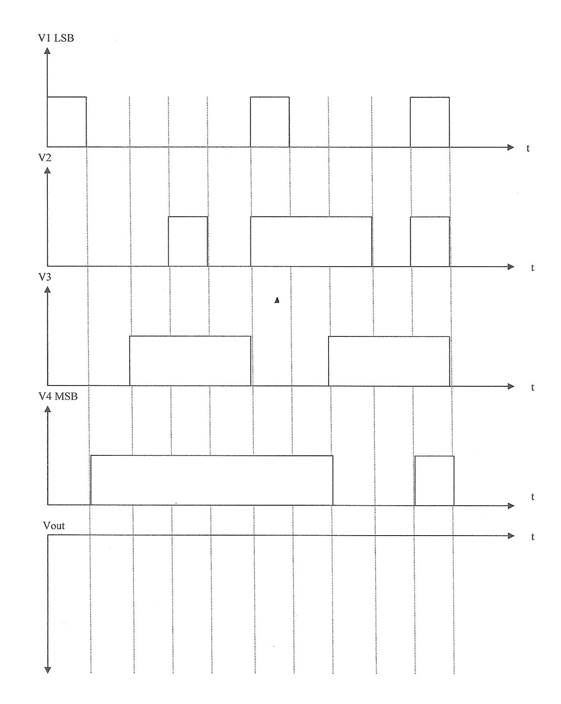
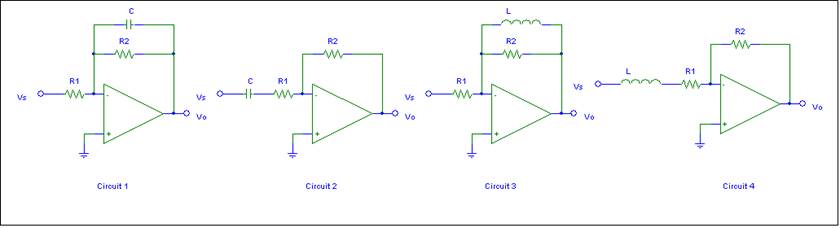
3. Active Analog Filter Topologies
You already know from our class discussions that Circuit 1 is an active analog Low-Pass
Filter. For each of the remaining three
circuits, state whether the circuit will function as a low-pass or high-pass
filter. Each of your answers must be
accompanied by a brief explanation and justification incorporating the
frequency dependent characteristics of the reactive circuit elements. That is you should look at the asymptotic
impedance of the L and C
if the input signal the frequency is very low or very high. No equations
are required!
3.
You decide to have a loud noisy party this
weekend with great music instead of studying EE 2212 or at least delay your
studying until the next day or whenever you recover. Suppose your 300 watt audio system yields an
80 dB signal as measured by the police in response to a noise ordinance
complaint by a neighbor who you should have invited to your party. http://www.industrialnoisecontrol.com/comparative-noise-examples.htm
(a) If the noise ordinance
limit is supposed to be 65 dB at the lot line, at what power level should you
run your system?
(b) Suppose you suggest to
the police , politely of course, so that you can avoid getting a minor for
other possible infractions at your party,
that the noise measurement be taken further away than the lot line. As an engineering student doing well in EE
2212, how much further away should the noise measurement be taken? You may assume that measured audio power is
proportional to 1/r2 where r is the distance from your speakers to the
point of measurement. Your answer will
be a distance ratio.
Many municipalities prohibit
sustained noise that exceeds a certain decibel level. The decibel limits are
set according to the time of day and the neighborhood zoning. When a neighbor
complains, police place decibel level monitoring equipment on an estimated
property line and take a reading.
4. Similar to
Problem 2 in the design approach. Since
I have been taking
guitar lessons (I am not very good which means I should practice more). Again use summing amplifier design ideas for guidance to design the electronic preamplifier for an
electric guitar.
![MCj04079760000[1]](ProblemSet2_files/image011.gif) There are six strings on an electric guitar and their
frequency and musical note
relationships are shown in the table. Each of the magnetic pickups for the six strings
will be modeled as six signal sources v1(t), v2(t), v3(t),
v4(t), v5(t), and v6(t).
There are six strings on an electric guitar and their
frequency and musical note
relationships are shown in the table. Each of the magnetic pickups for the six strings
will be modeled as six signal sources v1(t), v2(t), v3(t),
v4(t), v5(t), and v6(t).
DESIGN an operational amplifier system (guitar preamp/audio equalizer ) such that
the resultant output, which you would listen to as the sum,
meets the individual string
amplitude specifications given in the last row
of the table. .
Again, assume an ideal
operational amplifier which allows you to use summing point constraints,
however resistor values must be compatible with a mA 741, that
is all resistors > 2kW. Your design must include a detailed,
well-labeled circuit diagram showing six inputs; one for each string’s magnetic
pickup transducer.
|
String 1 High E |
String 2 B |
String 3 G |
String 4 D |
String 5 A |
String 6 Low E |
|
v1(t) |
v2(t) |
v3(t) |
v4(t) |
v5(t) |
v6(t) |
|
f1 > |
f2 > |
f3 > |
f4 > |
f5 > |
f6 |
|
14 dB |
20 dB |
6 dB |
-6 dB |
26 dB |
30 dB Nice bass boost |
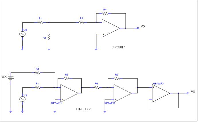
5. From an old quiz.
For each of the two separate circuits shown below, obtain an expression for the
voltage gain defined by
![]() . Assume ideal
operational amplifiers. Use summing
point constraints. Also observe that
Circuit 1 is best solved by using a Thevenin
equivalent circuit for the input network, node defined by R1, R2, and R3.
. Assume ideal
operational amplifiers. Use summing
point constraints. Also observe that
Circuit 1 is best solved by using a Thevenin
equivalent circuit for the input network, node defined by R1, R2, and R3.
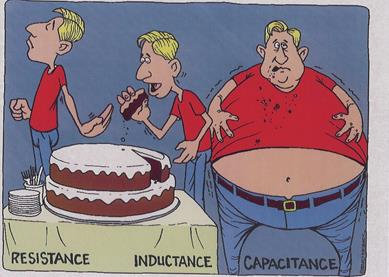
![]() These cartoons obtained
from a friend raiding a secret stash of cartoons at a well known laboratory
instrument company.
These cartoons obtained
from a friend raiding a secret stash of cartoons at a well known laboratory
instrument company.
UNITS ARE ALWAYS AN ISSUE TO REMIND YOU OF
THE BASIC CIRCUIT ELEMENT DEFINITIONS
This may help with your
understanding of DACs and ADCs

To
 BBBBBBBBBBBbbbbbbbbbb
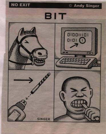
A

BASE 

BTO
SUPPORT YOUR UNDERSTANDING OF dB
AN IMPROVED PHYSICS I LAB
And more from my files of good stuff:
And
last but not least. General wisdom of the ages because I am not a fan of the
continual pain in the butt requests to update something or other in WINDOWS.